Home /
Expert Answers /
Finance /
figure-2-shows-a-differential-output-amplifier-implemented-in-18-nm-finfet-technology-assume-vdd-pa266
(Solved): Figure 2 shows a differential-output amplifier implemented in 18 nm finFET technology. Assume VDD = ...
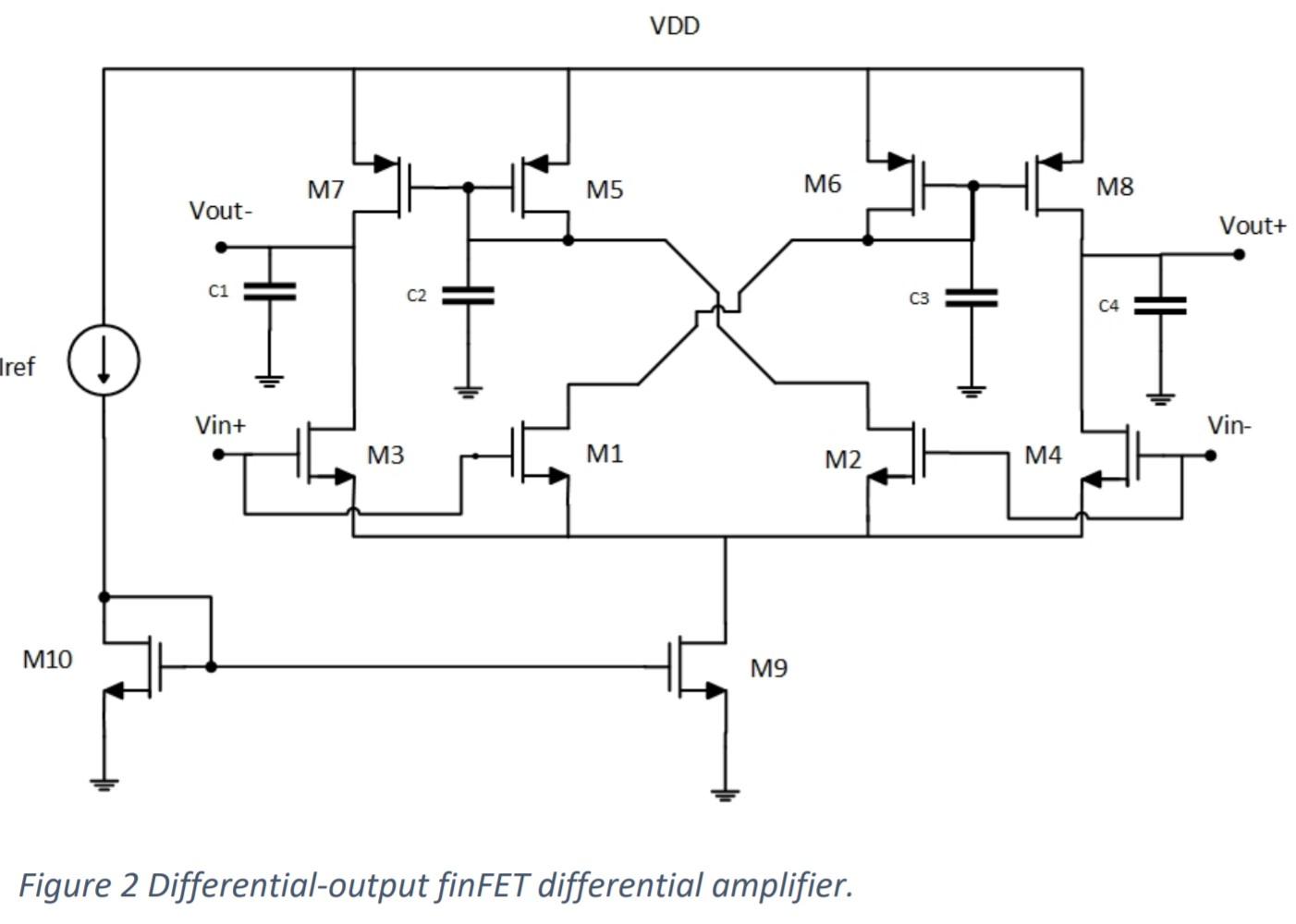
Figure 2 shows a differential-output amplifier implemented in 18 nm finFET technology. Assume VDD = 1 V, Iref = 40 µA, nfinp = 150 for the pMOS, nfinn = 100 for the nMOS transistors, and C1 = C2 = C3 = C4 = 1 pF.
a) Derive an expression for the small-signal transfer function Vout+(s)/(Vin+(s) – Vin-(s)).
b) Evaluate the low-frequency voltage gain and all poles and zeros.
- = - Problem 2. Figure 2 shows a differential-output amplifier implemented in 18 nm finFET technology. Assume VDD = 1 V, Iref = 40 u?, nfinp = 150 for the PMOS, nfinn = 100 for the nMOS transistors, and C1 = C2 = C3 = C4 = 1 pF. a) Derive an expression for the small-signal transfer function Vout+(s)/(Vin+(s) - Vin-(s)). b) Evaluate the low-frequency voltage gain and all poles and zeros. = 1
VDD M7 M5 M6 M8 Vout- Vout+ 75 c1 C2 C3 C4 1 ref ( Vin+ Vin- M3 M1 M2 M4 M10 M9 Figure 2 Differential-output finFET differential amplifier.

