Home /
Expert Answers /
Finance /
explain-step-by-step-the-working-logic-of-the-attached-control-chart-in-detail-4-a-9-l1-l1-43-0-pa494
(Solved): Explain step by step the working logic of the attached control chart in detail. 4.a.9/L1 L1/ 43.0 ...
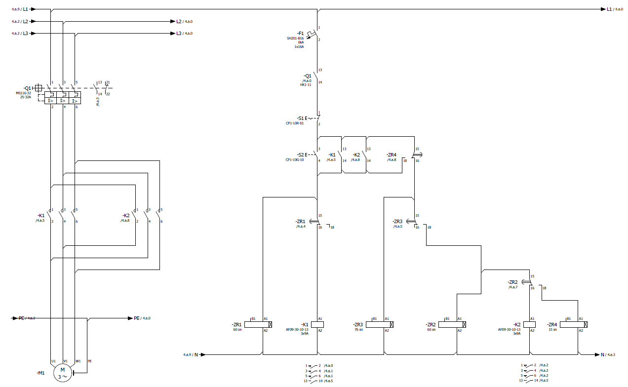
Explain step by step the working logic of the attached control chart in detail.
4.a.9/L1 L1/ 43.0 4.a.2/2 12/4.0 4.a.2/L3 3/42.0 / -F1 SH201-B16 ERA 1x16A 13 -Q1 Ma. HKI-11 14 -Q1HHL MS116 32 25-32A 13 34 12 3 I> -S1 Er- CP1-10R-01 13 13 15 -S2E-- CPI-10G-10 -K1 Mas -K2 -ZR4 AaB 4 14 4.8 14 18 16 15 15 -Ki Mas -K2 Ma. 6 -ZR1 Ma. -ZR3 Ha5 74 ??. ?? is 715 18 15 -ZR2 M.a.7 A 16 18 PEA PE/ 43.0 ! BI AL 181 Al BI Al AI 181 Al -ZR1 60 sn -K1 AF09-30-10-13 39A WOM -ZR3 76 s -ZR2 60 sn -K2 AF09-30-10-13 39A -ZR4 15 sn AZ A2 AZ AZ A2 4.a.9/N = N/ 42.3 1 vi WI PE M -M1 12 M.2.0 34 M.a.1 506 Ma. 13/14 M.a. 102 M2 322 56 M2 13/14 M.
